Boxford Cad Cam Design Tools Serial
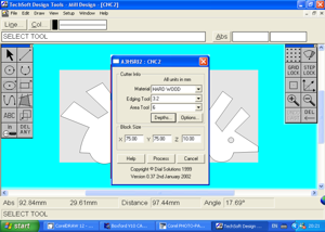
Computer aided design This provides a number of intuitive tools which allow the user to input a series of straight lines, arcs and threads to draw their desired component which automatically conforms to turning requirements. Includes manipulation tools to edit, move, delete or add new elements to existing designs. Additional fillet and chamfer tools are also available. Provides automatic dimensioning, and 3D views, in either solid rendered or wire frame, plus a choice of rendered material finishes.
Allows animated or manual user rotation around any axis and capability to print all 2D and 3D views. Component profiles can also be imported from a most third party CAD packages.
Test midot projti onlajn 15. Trusted Windows (PC) download Boxford CAD CAM Design Tools 5.0. Virus-free and 100% clean download. Get Boxford CAD CAM Design Tools alternative downloads.
Hi All the quotes you highlight are from someone who said he converted a 125TCL of unknown vintage. I completely converted my 160 a long time back. Whilst initially leaning towards maintaining manual control from the front panel, I decided that it would involve a lot more wiring complexity and everything I might want to do manually could be easily achieved by using the keyboard to jog axis or using the MDI line.
My experience using the lathe afterwards confirmed this, the only time I would have used manual would be to say face up a billet prior to setting up for a job run, MDI line or jogging is fine for this. I should have updated when I finished my conversion, but like everyone else I got busy using it. So here go the basics. (It covers conversion to run under Mach3, it will run under EMC2 but the setting described are Mach specific) Assuming that you have full manual control from the front panel, the first 2 things you need to order are a Opto isolated breakout board and an opto isolated Spindle board.
I got mine from. They work, are made in UK and are cheaper than US boards, especially with exchange rate dropping They take about a week to arrive, the guy Roy makes them up to order.
What you need is and I have attached a picture of the finished conversion showing these boards mounted under the cabinet fan Once you have the boards it is easy to get the axis running quickly. I just cut the 12 pin plug, which incorporates X Z and A (ATC) in the top 6 pins, in half and replaced the top half with a 6 pin plug from an old computer PSU and ran the cables straight to the stepper outputs on the opto port board. I set up the ATC as the B axis under Mach and set the shortcut keys to jog it on Page Up and Page Down on the keyboard. I have written a macro for M6 which automatically indexes the ATC to the correct tool position. If all your screw pitches etc are the same as mine it should work straight off, if not you may have to tweak the settings. The limit switches are all connected in series and attached to one input on the board. It doesn't matter which one tripped, that will be obvious from where the carriage and slide are.
The interlocks ( cover and pulley cowl )are similarly connected in serial to the Estop circuit in Mach. I did not connect the Estop button on the front panel, because it gave weird side effects with the 24v system being permanently latched. Since hitting it will knock out the 24v which in turn will stop the charge pump on the opto board and prevent any movement, that was good enough The index disc will need the slot opening out to 6mm. If you have a milling machine, just a question of centering it on the hole above the slot and milling out a grove of 6mm through the existing slot and that hole. If you want to do a lot of screwcutting you may need to cut 3 further slots and use the timing pulse input, but mine runs fine at present with just one slot and the pulse from the lower optical switch fed to Mach.